LEAP#194 DIY ESP8266 DevBoard
With the funding of the MicroPython on the
ESP8266 campaign, my interest in the ESP8266 is rekindled!
I have an ESP-01 module lying around, but I'm a bit tired of wiring it up a breadboard again. So here is a little
"devboard" I whipped up on a 4x6cm protoboard and hot-glued to a business card holder.
Now it's plug'n'play - add power and plug in a USB serial adapter and I'm good to go.
As always, all notes,
schematics and code are in the Little Arduino Projects repo on GitHub.
read more and comment..
LEAP#193 PoV LED Shake Stick
This AT89S52-based "shake stick" kit pops up all over the place for a few dollars. I built it and hey, it works
great!
But it's not packaged to be easily re-programmed for other messages or graphics. So started my sleuthing.. which turned
into a fascinating story.
It seems the kit was originally designed and built as a uni project by Zheng Zhong Xing 兴向荣 (aka zhengzhongxing39)
studying Control Technology and Instruments/Principles and Applications at a Chinese University. Reportedly "...
soldering was troublesome, with lots of changes and no solid basic skills, so burned out the first board" ;-) But it
seems persistence paid off, and ended up commercialising the kit and starting electronics business and taobao store
where you can find this kit and many others.
As always, all
notes, schematics and code are in the Little Arduino Projects repo on GitHub, including my annotation of the source
code and schematic for the shake stick.
read more and comment..
LEAP#192 Sagrada Família model with LED effects
The Basílica i Temple Expiatori de la Sagrada Família
has been under construction since 1882. The magnitude of the vision driving the project - both physically and
creatively - is striking, especially at first hand.
Then you see the work in progress - the cranes, scaffolding, workers scurrying around the site. But that is what I
think really brings it to life. This is not a frozen, finished statement of something other-worldy. It's a vibrant
expression of the hope and aspirations of a whole bunch of people working together.
In other words, it is the ultimate maker project! Personally, I think it will be a sad day when someone declares it
actually "finished".
Now at the extreme other end of the maker-scale is this
neat little paper nano Sagrada Familia kit that I picked up in my travels.
I've "electrified" it to some extent with some LowVoltageGlowingLEDs
that animate the background, just running off a 1.5V supply. Although I think I could have slowed down the LEDs even
further.
A nice effect I think..
As always, all notes,
schematics and code are in the Little Arduino Projects repo on GitHub.
read more and comment..
LEAP#191 glowing LEDs on 1.5V
So for another project I wanted some "glowing" LEDs, ideally powered from a single 1.5V AA or AAA battery. That seemed
like an interesting challenge, especially when the forward voltage of the LEDs I'm using is about 2.1V.
I had a feeling I could cobble together a couple of ideas (Relaxation Joule Thief and RC Oscillator) .. and lo, it
works!
As always, all notes,
schematics and code are in the Little Arduino Projects repo on GitHub.
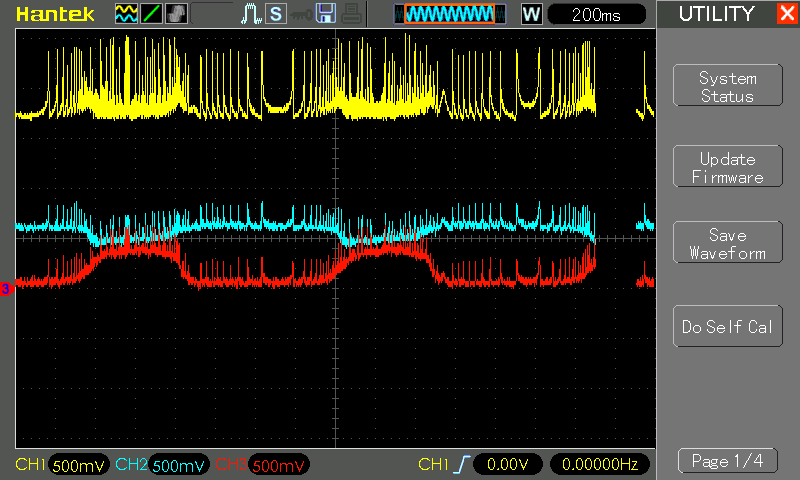
Here's a glimpse of the "modified oscillation". CH2 (red) is the LED cathode/transistor collector - as it rises and
falls the LED slowly switches off then back on.
For protoboard-based builds I tend to layout the schematic with PAD tools (Pencil-Aided Design) ...
read more and comment..


