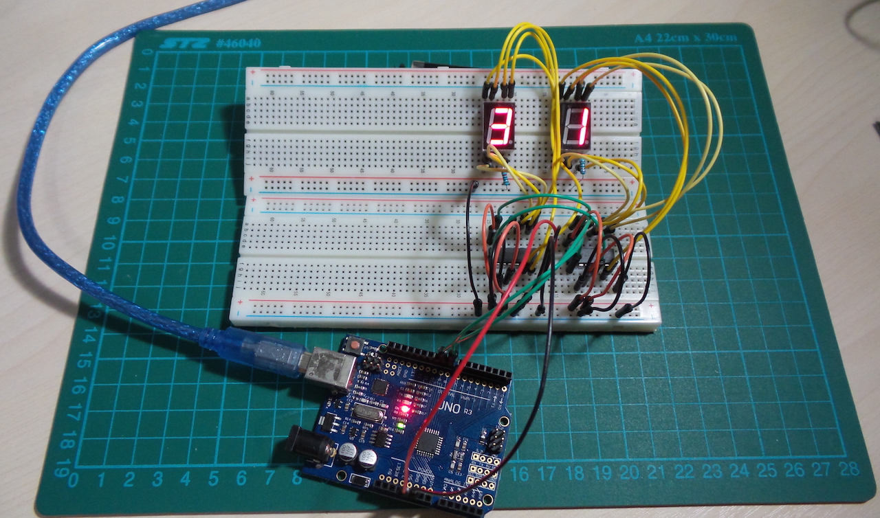
LEAP#199 CD4026 Bucket-brigade LED driver
This is an extension if the ideas in #196,
demonstrating how it's possible to build a "bucket-brigade" of CD4026 chips to drive an arbitrary number of 7-segment
LEDs with a single data line.
It just requires the carry-out from the first CD4026 to be chained as the clock input for the second and so on.
As always, all notes,
schematics and code are in the Little Arduino Projects repo on GitHub.

read more and comment..
LEAP#198 Hall Effect Switch
Hall-effect sensors generally support one of three modes:
- switch - turn on in the presence of a magnetic field of a specified polarity
- latch - turn on in the presence of a magnetic field, and stay on until exposed to the reverse polarity
- linear sensor - output is proportional to the magnetic field strength
The chip is rated for continuous output current of 25mA, so that is sufficient to drive an LED (as demonstrated here). For other switching applications, the output can be used to switch a transistor or pull a microcontroller output low.
Testing with some neodymium magnets, I get a strong full-on when the south pole of the magnets are within 23mm directly to the front of the chip. The output remains on until I pull back to over 40mm.
A common use for Hall-effect sensors is to detect and measure rotation. A good demonstration of this is to sequence a PoV display as demonstrated in Great Scott's latest video - HACKED!: Old Fan becomes a POV Display
As always, all notes, schematics and code are in the Little Arduino Projects repo on GitHub.

read more and comment..
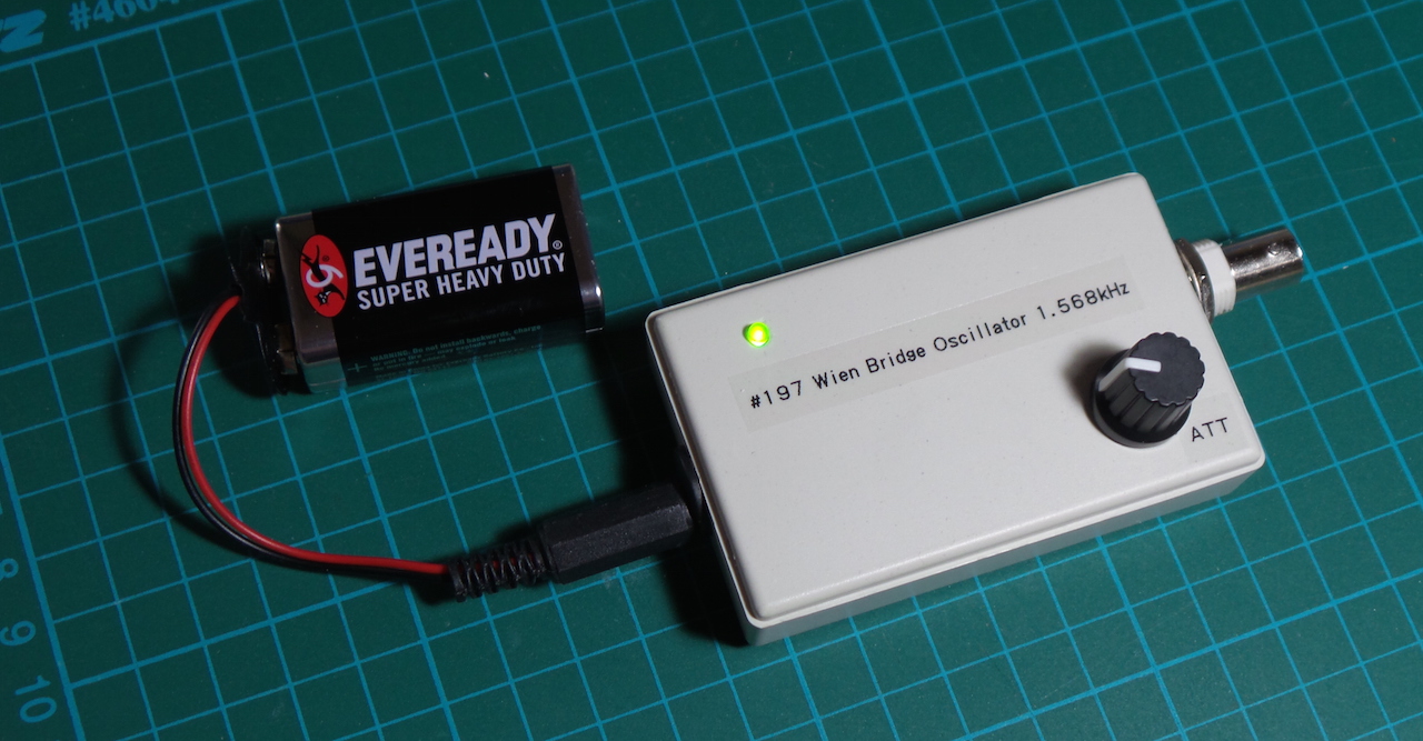
LEAP#197 Wien Bridge Audio Tone Generator
A Wien bridge oscillator is essentially an RC Band
Pass Filter with a high Q factor at the resonant frequency, and generates a nice sine wave. I wanted a simple
audio-frequency test signal generator, and a Wien Bridge turned out to be perfect for the job.
As always, all notes,
schematics and code are in the Little Arduino Projects repo on GitHub.
A good old LM324 does triple duty in the circuit:
- a non-inverting amplifier with a gain of ~3 provides the feedback required to sustain the oscillator
- one unit buffers a half-supply voltage to provide a "virtual ground" for the non-inverting amplifier
- a third unit buffers the output signal to avoid load interference with the oscillator
The result is a pretty decent sine wave at ~1.574kHz, very close to the theoretical resonant frequency of 1.592kHz.

read more and comment..
LEAP#196 Driving a 7-segment display with CD4026 Counter
Here's yet another way to drive a 7-segment single-digit display unit - using a CD4026.
The CD4026 is a 5-stage Johnson decade counter with decoded 7-segment display outputs and display enable. With RESET
and CLOCK INHIBIT low, and DISPLAY ENABLE IN high, the 7-segment display outputs progress through the 0-9 sequence on
the rising edge of the CLOCK pulse.
It's an interesting alternative to a shift register for driving a 7-segment LED (as in the ShiftDrive
project). While a latched shift register provides random addressing and clean transitions to any digit, it requires
the 7-segment display outputs to be decoded externally (like in code). On the other hand, the CD4026 takes care of the
decoding, and external circuits just need to send a counter pulse.
As always, all notes, schematics
and code are in the Little Arduino Projects repo on GitHub.

read more and comment..