LEAP#204 Type K Temperature Logger
I'm working on an idea where I need to measure temperatures to around 500°C - above those typically supported with
semiconductor sensors or thermistors.
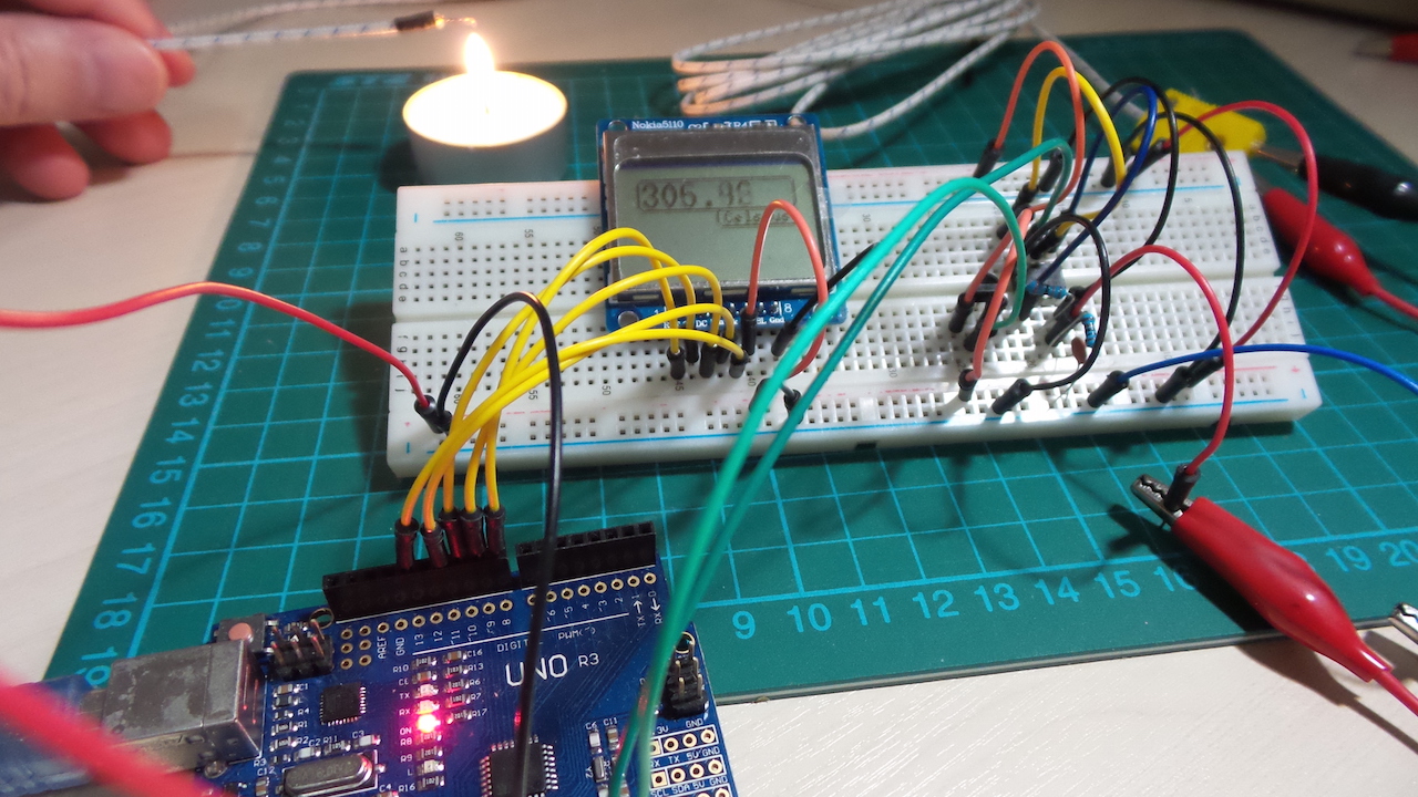
This project demonstrates the basic approach using an Arduino as the "temperature logger". I'm using a K Type
thermocouple that's rated up to 700°C. Since thermocouples only measure a differential temperature, I'm also using an
LM35 to provide the cold-junction baseline. The temperature measurement is displayed on a 5110 LCD.
As always, all
notes, schematics and code are in the Little Electronics & Arduino Projects repo on GitHub.
read more and comment..
阿部真央 Don't let me down
One of the best finds in the racks at Tower Records Fukuoka福岡市. It's been years since I last got to browse a record
store in Japan; I'm glad they still exist, with stacks of CD players queued up to sample. And a huge relief to see the
indie rock scene is just as vibrant as I remember!
read more and comment..
LEAP#203 Homopolar Motor
What happens when electric fields cut across magnetic fields? A force is generated, and the homopolor motor is the
classic demonstration.
As always, all notes,
schematics and code are in the Little Electronics & Arduino Projects repo on GitHub.
read more and comment..
LEAP#202 LM3915 Audio Level Kit
The LM3915 is a useful IC for simple audio level displays. This is a cheap kit build which largely follows the
reference circuits in the datasheet.
As always, all notes,
schematics and code are in the Little Electronics & Arduino Projects repo on GitHub.

read more and comment..