LEAP#210 Pump up the Jam!
This is a super cheap amplifier kit built around the TDA7297 15+15W dual bridge amplifier chip. All the other parts in
the kit are essentially the basic supporting components for the TDA7297.
Performance is very good, although my impromptu speaker boxes don't do it justice. They need better baffles at least,
but I can hardly blame Straits Preserves for not making marmalade boxes
to the specification of speaker enclosures!
As always, all notes,
schematics and code are in the Little Electronics & Arduino Projects repo on GitHub.
read more and comment..
LEAP#209 a funky little LED display
I found this interesting LED display at Sim Lim Tower, and grabbed one to test. The LED unit combines 7 x 7-segment
display (no decimal points) and 7 indicator LEDs (Red-Green-Yellow).
It is marked as "72R02PHIL T9717". I have no idea what that means(!), and of course there's no sign of a datasheet on
the net, so pinouts needed a bit of reverse-engineering. All in all, an interesting display unit for a combination of
numerical and status display.
As always, all
notes, schematics and code are in the Little Electronics & Arduino Projects repo on GitHub.
read more and comment..
LEAP#208 Single Stage FM Transmitter
I've been experimenting with FM, and the hardest thing to get right tends to be the hand-wound coils. So to get a
baseline, I picked up a 1-transistor kit during a recent visit to Sim Lim Tower.
As always, all notes,
schematics and code are in the Little Electronics & Arduino Projects repo on GitHub.
read more and comment..
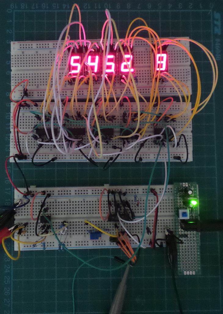
LEAP#207 Frequency Counter
Testing a CMOS frequency counter circuit with a 100Hz - 5MHz range.
I found this circuit published in Electronics magazine (Sep 16 1976). It's a classic demonstration of the CD4026
"bucket-brigade" and CD4047 astable oscillator.
The frequency counter is governed by a CD4047 oscillator. Since this offers a clean 50% duty cycle, it is ideal for
flipping the circuit between two modes: sampling period; display period.
As always, all
notes, schematics and code are in the Little Electronics & Arduino Projects repo on GitHub.
read more and comment..