LEAP#247 pedalSHIELD UNO
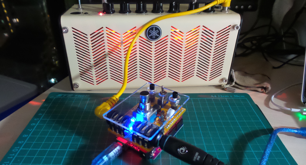
In the AudioDSP project,
I built an Arduino pedal/DSP unit based on the Electrosmash pedalSHIELD design.
It worked well enough that I wanted to build the “real thing”, not only to give myself a good baseline on expected performance,
but also to payback Electrosmash in a small way. Good OSH deserves support!
As always, all notes, schematics and code are in the Little Electronics & Arduino Projects repo on GitHub
read more and comment..
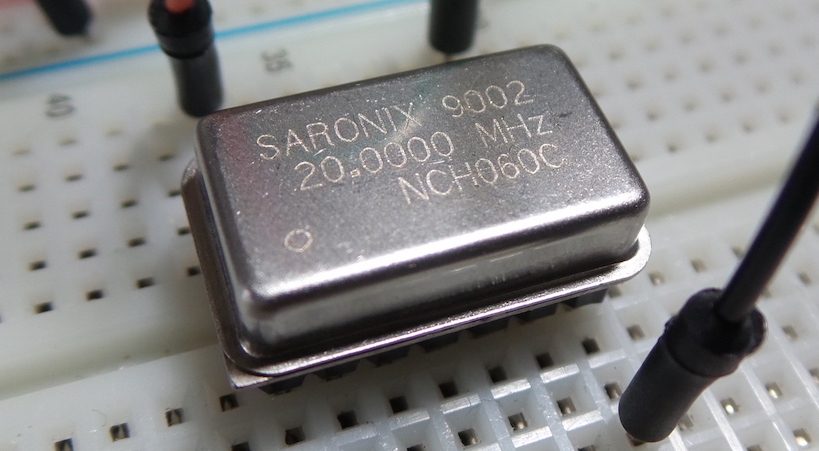
LEAP#246 CMOS Oscillators
4-pin CMOS oscillators - like the SaRonix NCH060C I’m testing here - contain all the circuitry
necessary to produce an oscillation when voltage is applied.
Internal details are hard to find, but I’m guessing NCH060C is a combination of
crystal resonator with CMOS inverter gate and buffer.
As always, all notes, schematics and code are in the Little Electronics & Arduino Projects repo on GitHub
read more and comment..
LEAP#245 Generic Curve Tracer
I borrowed this general curve tracing circuit from
stoneslice’s prototype and video.
Rather than rely on an AC power supply, this uses a simple DC-powered oscillator to drive a test signal across the device under test.
It features a DPDT switch to toggle and compare two devices under test.
Although uncalibrated so not particularly good for accurate measurements, it generates nice plots
for resistors, capacitors, and diodes.
As always, all notes, schematics and code are in the Little Electronics & Arduino Projects repo on GitHub
read more and comment..
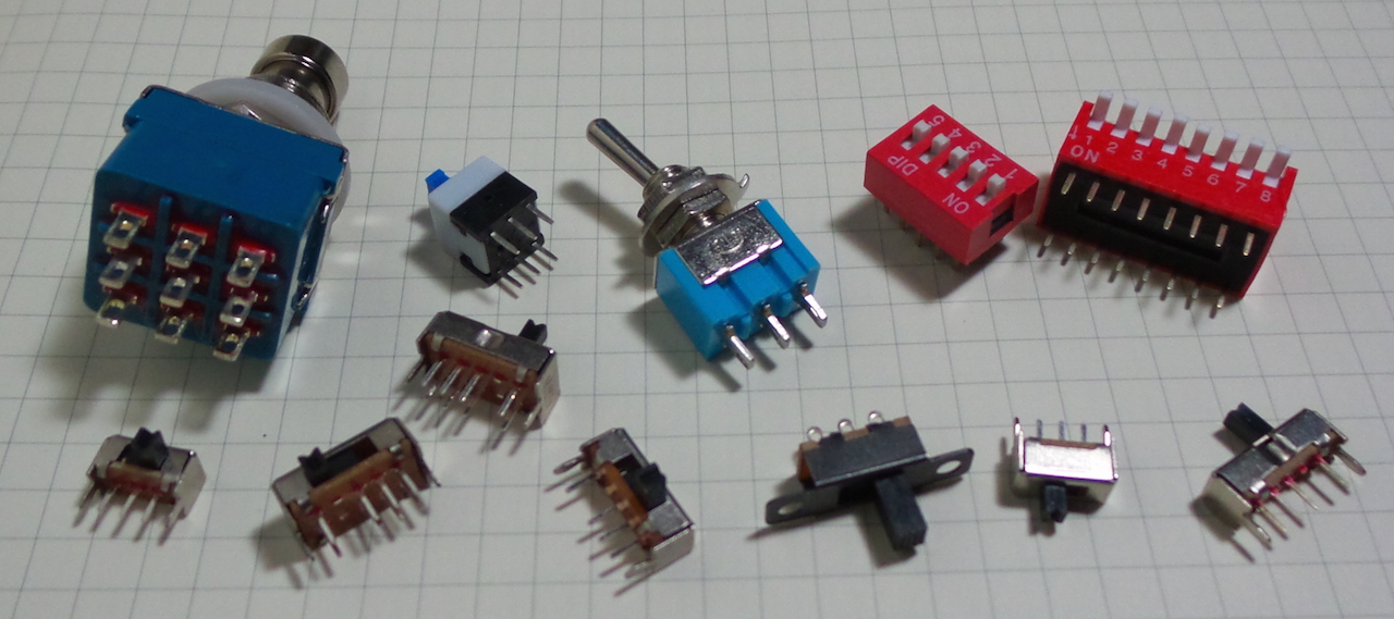
LEAP#243 Switches
Switches are the most basic of input devices for electrical and electronic systems.
Thorough coverage of the variety of switches can be found in works such as
Charles Platt’s excellent Encyclopedia of Electronic Components Volume 1,
and John M. Hughes’ Practical Electronics: Components and Techniques.
These are my notes on nomenclature and specific components - available in the Little Electronics & Arduino Projects repo on GitHub
read more and comment..