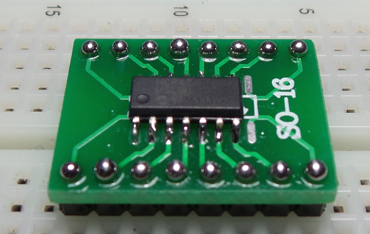
LEAP#264 MCP42010 Digital Pot
More of my minor obsession with digital potentiometers!
This time the dual 10kΩ version of the MCP42010 with SPI control.
I really like this unit - cheap and very flexible. I ended up using it in a few applications. Stay tuned!
As always, all notes, schematics and code are in the Little Electronics & Arduino Projects repo on GitHub
read more and comment..
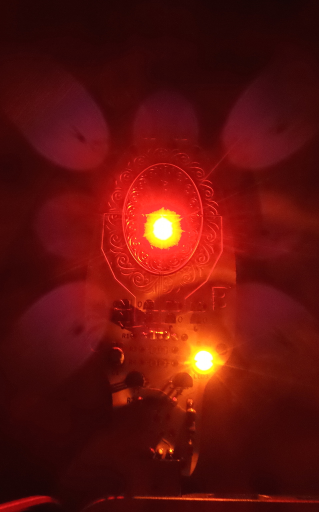
LEAP#263 Boldport LigEmDio
A USB-powered LED tester kit featuring a classic BJT constant current source.
Another beautiful board from the Boldport Club - the embossed patterns are truly marvelous.
As always, all notes, schematics and code are in the Little Electronics & Arduino Projects repo on GitHub
read more and comment..
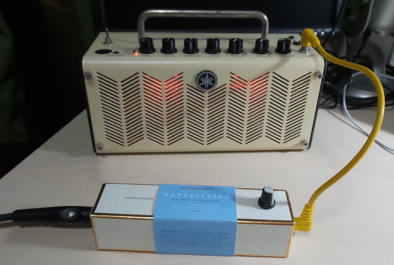
LEAP#262 Bazz Fuss Chocolate Noisette
The Bazz Fuss is about the simplest distortion circuit I’ve ever seen that in fact yields pleasing results.
After a few experiments comparing configurations on a scope I ended up using two S9013 in Darlington configuration.
The result is decidedly luscious, so the final build went in a suitably sweet chocolate noisette box.
As always, all notes, schematics and code are in the Little Electronics & Arduino Projects repo on GitHub
read more and comment..
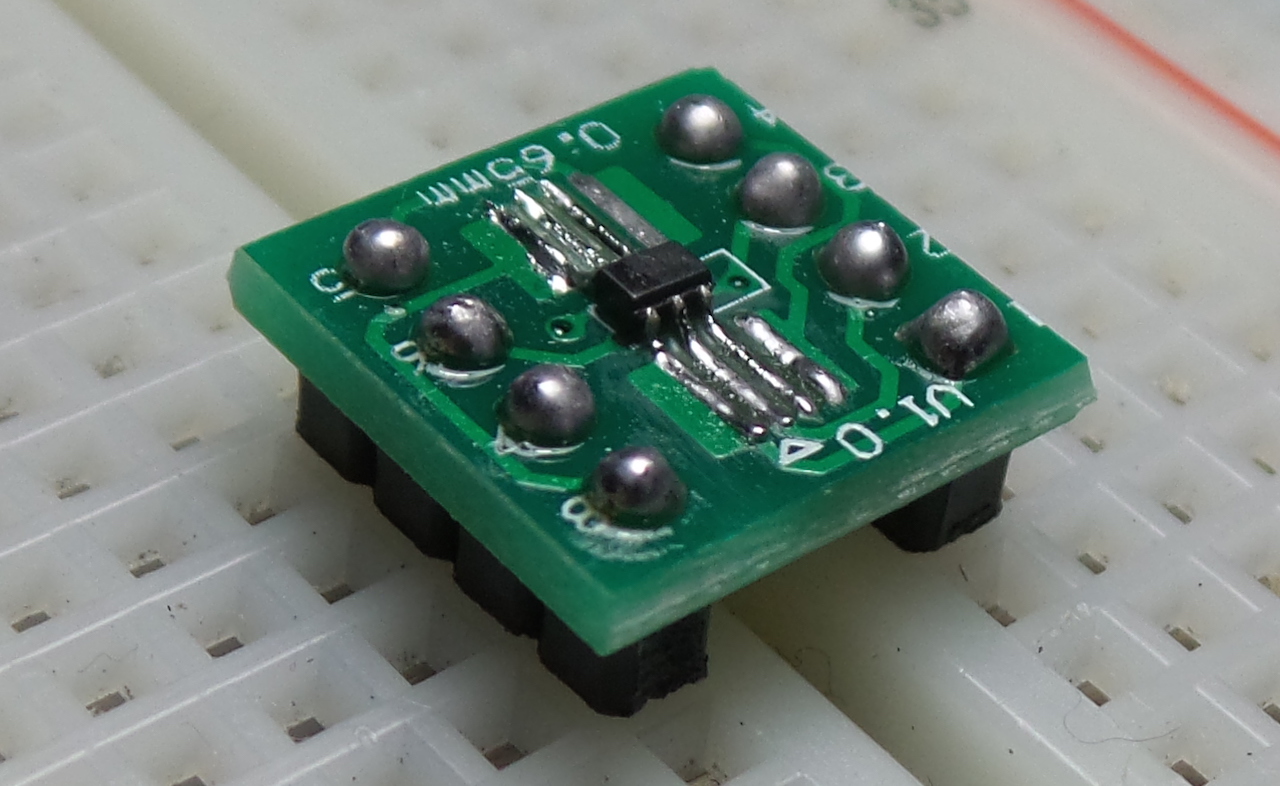
LEAP#261 MCP4017 Digital Pot
I’m having a minor obsession with digital potentiometers!
The next I’ve tested is the MCP4017T-104E/LT (100kΩ rheostat version).
It comes in a very small SC70 package and works as advertised.
Although conveniently controlled with I²C, there doesn’t appear to be any way of setting the address.
That and the fact that it is only rated for 2.5mA make it a bit limited in scope of application.
As always, all notes, schematics and code are in the Little Electronics & Arduino Projects repo on GitHub
read more and comment..