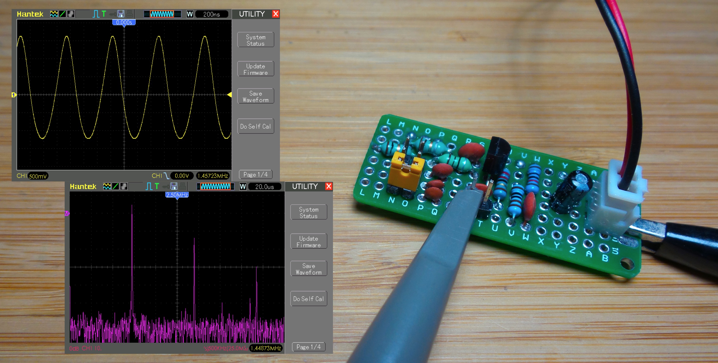
LEAP#418 Hartley Oscillator
The Hartley oscillator is distinguished by a tapped inductor to provide feedback (the Colpitts oscillator uses capacitors).
I got some decent results on a breadboard, even better on protoboard, using a basic Hertley design with RF chokes for inductors and a BJT.
As always, all notes, schematics and code are in the Little Electronics & Arduino Projects repo on GitHub
read more and comment..
LEAP#417 Playing Sound Samples with Arduino
Microcontrollers typically don’t have a lot of on-board memory, so the idea of playing audio samples is generally out of reach without somehow solving the storage issue or delving into synthesised sound.
But it is possible to play (very) short samples. In this example I’m playing an 8kHz, 8-bit sample stored in flash memory, using the PCM library to modulate a PWM output accordingly.
As always, all notes, schematics and code are in the Little Electronics & Arduino Projects repo on GitHub
And here’s an Uno pretending to be a phone, just to prove the point…
read more and comment..
LEAP#416 Simple Line-follower
Here’s a neat little line-tracking car kit that’s widely available from the usual online sources. There are a number of variations around, but they all share the same essential control circuit.
It is a simple example of the most basic class of Line Follower Robots, using an op-amp comparator as the “brain” to take feedback from left and right light-dependent resistors to control left and right motors accordingly.
If you know someone just getting into electronics and looking for something a little more challenging than soldering an LED blinky, then this kit would be a great next step. It’s hard to get wrong, introduces a few more exotic components, and it’s usually available cheap enough to be a nice stocking stuffer. Most importantly - it actually works!
As always, all notes, schematics and code are in the Little Electronics & Arduino Projects repo on GitHub
And if you want to watch it go round a test track for 30 seconds, be my guest … ;-)
read more and comment..
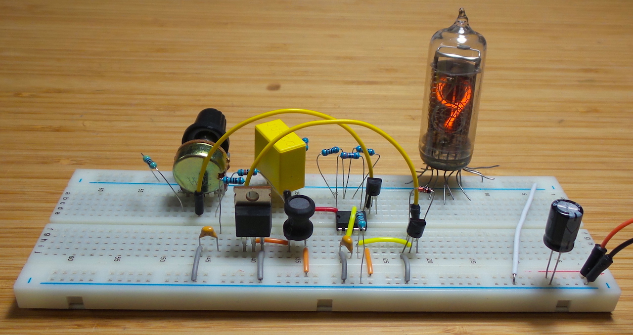
LEAP#415 Testing Nixies with a 555
I found some Nixie tubes at a reasonable price and snatched them up. I’m sure there’s a project waiting for them, I just haven’t figured out what it will be yet - a clock is a bit obvious!
But first to test them out, and I stumbled across a few boost power supplies using a 555 timer. While these may not be the efficient or precise for a “real” circuit, they are certainly interesting enough for a quick test.
And it works quite nicely on a breadboard!
As always, all notes, schematics and code are in the Little Electronics & Arduino Projects repo on GitHub
read more and comment..