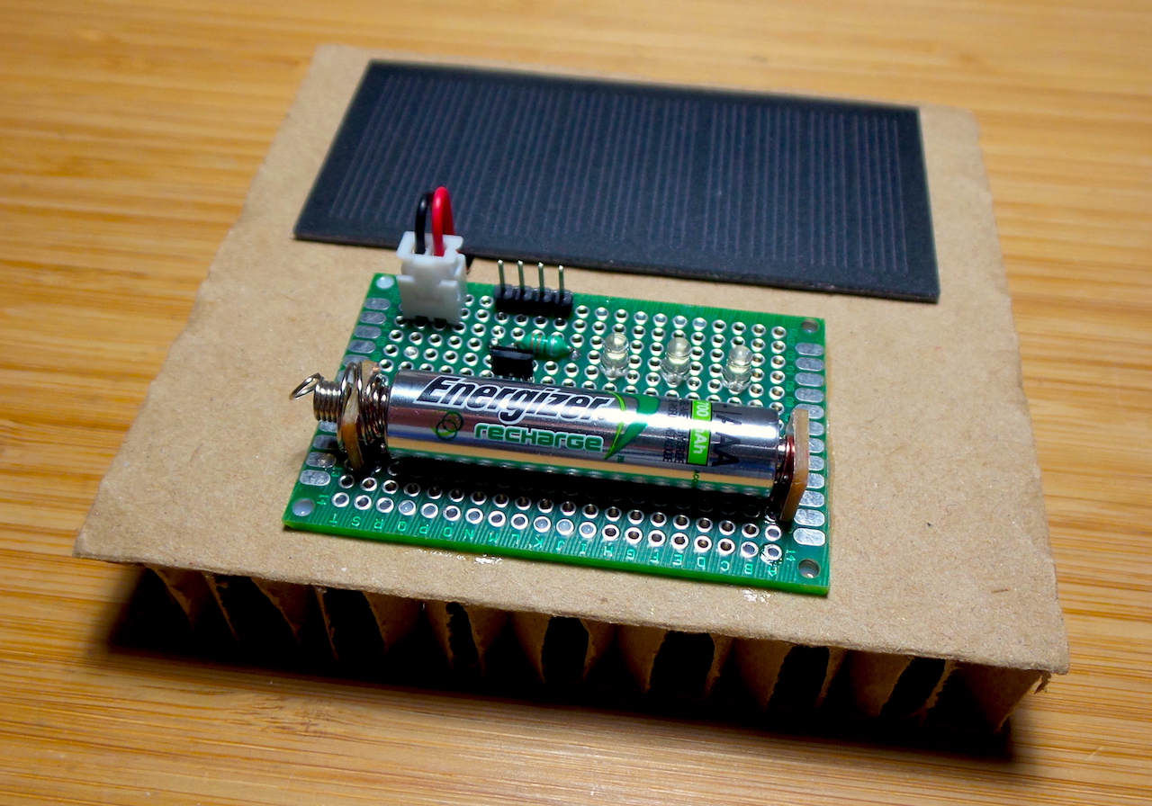
Inside most solar-powered garden lights is an ingenious little circuit comprising a rechargeable battery, solar cell, inductor, LED and a little IC that does all the magic:
- when voltage is detected from the solar cell, the LED is off and the battery will charge
- as the solar cell voltage drops off (gets dark), the chip runs a switching converter (using the inductor) to boost the voltage from the 1.x V battery sufficient to drive the LED
- when the battery voltage falls too low, it tuens off the boost converter to prevent over-discharge
The chips that do the work are typically 4-pin TO-94 packages and come from various sources. Some of the most common are the QX5252 and YX805. I’m using a QX5252 here as it is the one I found a reasonable datasheet for.
There are DIP versions of these chips that have an additional light control pin that can either be used as a simple on-off, or to adjust the PVC voltage at which the LED cuts-off. I’m not using this as I have the TO-94 package version.
This project is a simple demonstration build of the standard solar-powered LED circuit. As always, all notes, schematics and code are in the Little Electronics & Arduino Projects repo on GitHub
A quick demo of the switching based on light conditions:
