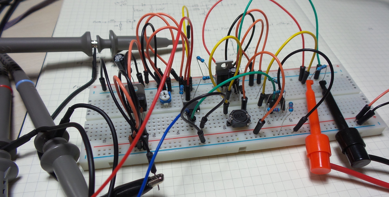
Testing a very basic inverting buck-boost converter controlled by an ATtiny85.
The basic inverting buck-boost circuit uses an inductor to build up an electromagnetic field during the switch-on period, and dump this energy into the capacitor during the switch-off period. The diode provides steering.
As always, all notes, schematics and code are in the Little Electronics & Arduino Projects repo on GitHub
