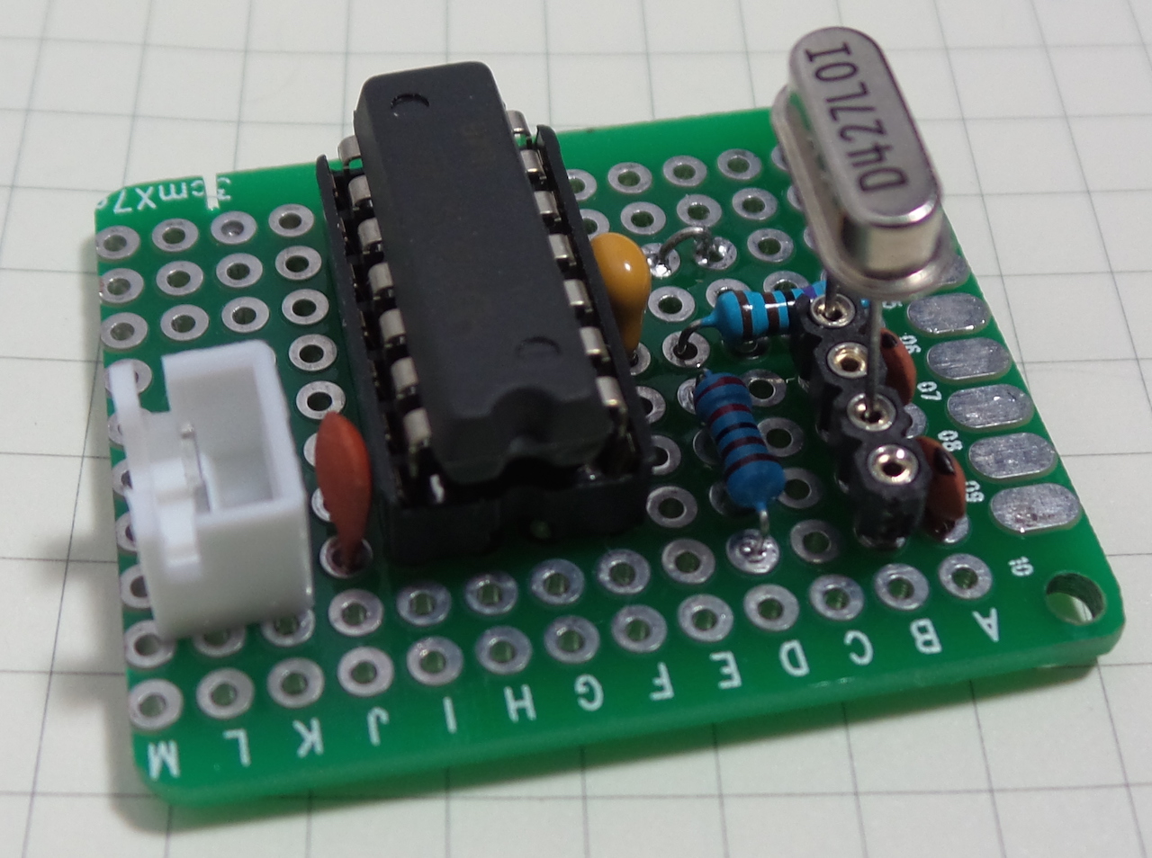
The Pierce oscillator can be implemented using a minimum of components, typically: a digital inverter, one resistor, two capacitors, and a quartz crystal.
The term “Pierce Gate Oscillator” generally refers to circuits where the digital inverter is implemented as a CMOS gate (inverter or NOR).
This is a very common arrangement, and is used with microcontroller chips to provide the external clock source.
The example build here uses a 4.273MHz crystal resonator and a 74LS14 schmitt inverter.
As always, all notes, schematics and code are in the Little Electronics & Arduino Projects repo on GitHub